VAV Box Not Cooling? What to Check Before Replacing the Controller
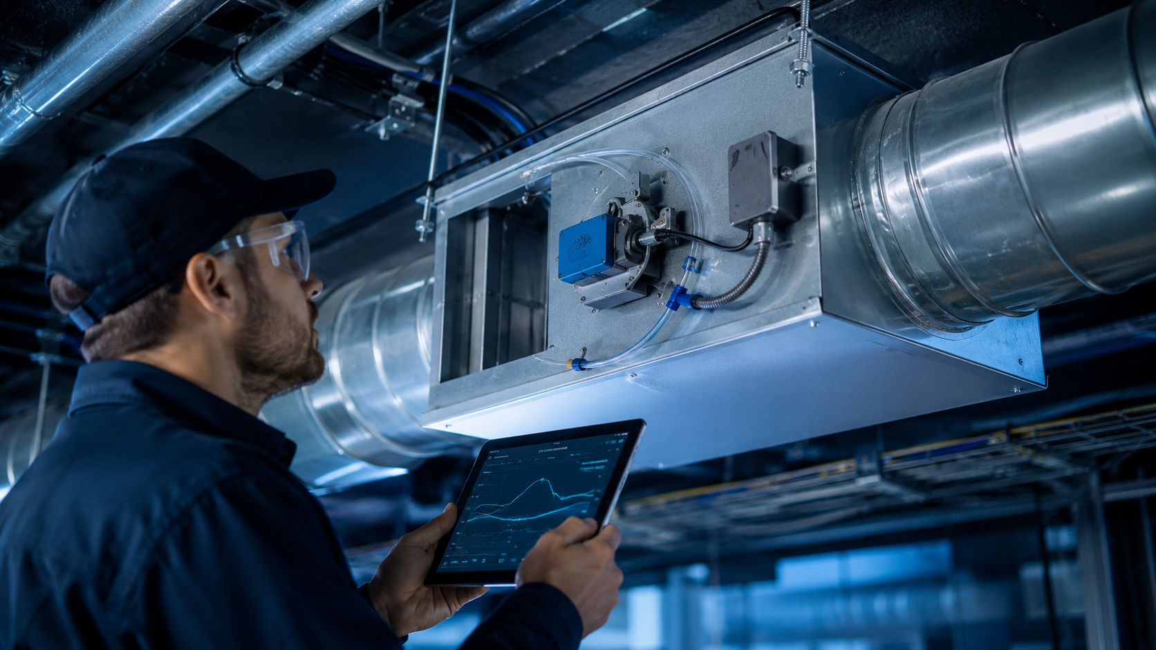
VAV box not cooling the zone? A warm zone and a 100% VAV damper command do not prove the controller has failed. Follow the airflow and control sequence first so you can separate an upstream airside problem from a local mechanical, sensor, communication, or programming fault.
Quick Answer
If a VAV box is not cooling, first confirm a real cooling demand, identify unintended BAS overrides, and compare airflow setpoint with actual airflow. Then verify AHU static pressure, physical damper movement, airflow sensing, reheat, the zone sensor, controller power, and communication before replacing the controller.
Table of Contents
- Quick Troubleshooting Checklist
- The Problem
- Why It Happens
- Nine Diagnostic Checks
- Symptoms, Evidence, and Next Tests
- How to Fix It
- Field Case: One Room, Two Controllers
- Closeout Verification
- FAQ
- Technical References
Quick Troubleshooting Checklist
- Confirm room temperature, effective cooling setpoint, occupancy, and mode.
- Record overrides and compare airflow setpoint with measured airflow.
- Check primary-air temperature, static pressure, and physical damper movement.
- Verify airflow sensing, approved balancing values, and unintended reheat.
- Check sensor mapping, power, communication, and shared-point ownership.
- Correct the demonstrated fault, release test overrides, and retest.
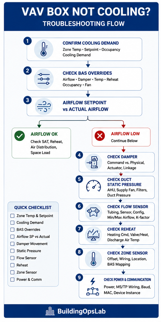
The Problem
A zone is warm, the BAS shows cooling demand, and the VAV damper appears to be open. It is tempting to blame the VAV controller or actuator.
But a VAV depends on the entire airside sequence. Low duct static pressure, incorrect airflow measurement, a mechanical damper problem, unwanted reheat, sensor error, BAS overrides, or communication issues can all create the same comfort complaint.
Why It Happens
Inadequate primary air, a stuck damper, unreliable sensing, unintended reheat, overrides, or an incorrect mode can produce the same complaint. Communication faults may prevent supervisory commands or shared values from reaching the terminal.
This guide focuses on pressure-independent terminals regulating measured airflow to a setpoint. Pressure-dependent, dual-duct, and fan-powered applications require their own sequences. Even a pressure-independent box needs sufficient available inlet pressure.
How to Diagnose It
1. Confirm the Cooling Demand
Check zone temperature, effective cooling setpoint, occupancy, cooling demand, and the current operating mode. Make sure the controller should actually be requesting cooling.
A warm complaint during warm-up, an unoccupied setback period, or a mode transition can look like a failed VAV even when the controller is following its programmed sequence.
2. Check for BAS Overrides
Look for overrides on airflow setpoint, damper command, zone temperature, occupancy, reheat, and fan command on fan-powered boxes. Review both the graphic and the underlying point status.
Record override source and purpose before changing it; release only authorized test or unintended overrides and restore automatic operation after testing.
3. Compare Airflow Setpoint to Actual Airflow
For a pressure-independent VAV, this is one of the fastest checks.
- High airflow setpoint and actual airflow follows: look beyond the VAV at supply-air temperature, space load, reheat, diffuser performance, or air distribution.
- High airflow setpoint and low actual airflow: check duct static pressure, physical damper operation, airflow sensing, and VAV configuration.
- Airflow reading does not change when the damper moves: investigate the pickup, tubing, sensor, scaling, and configuration before trusting the value.
4. Check the AHU and Static Pressure
If several VAVs cannot reach airflow at the same time, investigate upstream. Check supply-fan operation, VFD speed, duct static-pressure setpoint and actual value, supply-air temperature, filters, and major restrictions.
One affected zone often points toward a local issue. Multiple low-airflow zones can point toward a system-level problem. If static pressure is unstable or alarming, use the checks in AHU Static Pressure Alarm Keeps Coming Back? before increasing setpoints.
5. Verify the Damper Physically
Do not assume a 100% command means the damper is physically 100% open. Inspect actuator movement, shaft connection, linkage, mechanical stops, and damper blades.
Determine whether displayed position is a command, calculated position, or independent feedback. Verify mapping and use an approved test to compare output with movement, then release the test override.
6. Check the Airflow Sensor and Configuration
Inspect the pickup and tubing for damage, kinks, leaks, or moisture using product instructions. A steady airflow reading during damper movement may be legitimate if upstream pressure changes; compare operating conditions before condemning the sensor.
Compare minimum airflow, maximum airflow, heating airflow, K-factor, or equivalent configuration values against approved balancing or design information. Do not copy nearby-box values. Zero or calibrate only under prescribed manufacturer conditions; changing a coefficient to hide a restriction creates misleading data.
7. Check Reheat
Compare primary-air and terminal discharge temperatures where available; check reheat demand, command, and physical output. For fan-powered terminals, identify series or parallel operation and account for secondary-air mixing under the specific sequence.
A 0% BAS valve command does not prove the physical valve is closed. A leaking valve, failed actuator, incorrect output, or unintended override can keep heating the discharge air.
8. Verify the Zone Sensor
Compare the BAS temperature with a reliable field measurement when necessary. Check for sensor offset, wiring problems, poor location, heat sources near the sensor, or incorrect point mapping.
Before applying an offset, confirm that the reference instrument is appropriate and that the real problem is not local stratification, airflow distribution, or a misleading mounting location.
9. Check Power and Communication
Check BAS value age and quality; offline graphics may display old data. Verify local power, application state, and network type. For BACnet MS/TP installations, follow these BACnet MS/TP troubleshooting checks for polarity, baud rate, addressing, and trunk or router condition.
Loss of supervision does not prove loss of local control; verify actual operation. For upstream network symptoms, see BACnet Router Problems: Why Devices Disappear.
Symptoms, Evidence, and Next Tests
| Observed symptom | Evidence to collect | Next test |
|---|---|---|
| High command, low reported flow | Shaft movement, inlet pressure, airflow signal | Separate restriction or mechanical failure from measurement error. |
| Flow meets setpoint, room warm | Primary/discharge temperatures, reheat, room trend | Check delivered cooling, added heat, and distribution. |
| Several zones fail together | Affected branch, AHU status, static-pressure trend | Compare common upstream conditions first. |
| Controllers disagree about one room | Sensor source, value quality, mode, setpoints | Trace shared-point ownership and updates. |
These observations select the next test; none alone proves a failed controller.
How to Fix It
Correct the failure that the testing actually confirms:
- Low upstream airflow: correct the AHU, filter, fan, static-pressure, or duct restriction problem before changing the VAV controller.
- Damper command does not match movement: repair a confirmed loose shaft, linkage, mechanical stop, binding damper, actuator, or output problem.
- Airflow reading is unreliable: repair the pickup or tubing, correct scaling, and recommission airflow settings using approved balancing data.
- Reheat is active during cooling: remove unintended overrides and repair the confirmed valve, actuator, output, or sequence issue.
- Zone temperature is inaccurate: correct mapping or configuration, repair wiring, or replace a confirmed failed sensor.
- Controller is offline: restore confirmed power, wiring, network configuration, or trunk faults before considering controller replacement.
- Controller fault is confirmed: replace or reprogram it only after inputs, outputs, power, network, and the approved sequence have been verified.
After the correction, release test overrides and functionally test the complete cooling sequence. Confirm that zone demand changes airflow setpoint, actual airflow responds, the damper modulates, reheat stays off during cooling unless the approved sequence requires otherwise, and the zone temperature begins moving in the expected direction.
Field Case: One Room, Two Controllers
A documented service scope for a courtroom identified two controllers serving the same space: one handled the airflow damper and valve actuators, and the other controlled the fan-powered box. The proposed work was to share the correct room-sensor value and synchronize the sequences.
Evidence boundary: the record establishes the arrangement and proposed work. It does not establish a completed repair, measured cooling recovery, or a failed controller. No before-and-after temperature or airflow result is claimed.
Verify Point Ownership Before Reprogramming
Map each input and output owner. Plan value-quality, update, communication-loss, and recovery tests using the approved sequence.
| Function | Ownership and test |
|---|---|
| Room temperature | Identify the sensor and mapped source; compare both controllers with a room measurement. |
| Primary airflow | Identify the loop owner; compare setpoint, measured flow, command, and damper movement. |
| Valve and terminal fan | Identify output owners; verify physical response and specified interlocks. |
| Mode and setpoints | Confirm coordinated occupancy and effective setpoints; test shared-value loss and recovery. |
A separate scope involved relocating a sensor from outside the controlled courtroom to inside. Keep that issue separate: verify the served space and representative sensing location before treating a sensor offset as a solution.
Closeout Verification
- Record the original condition, each change, and applicable sequence or balancing reference.
- Release test overrides and verify automatic occupancy and setpoints.
- Trend room temperature, airflow setpoint and actual flow, damper command, available primary/discharge temperatures, reheat, and fan status.
- Confirm physical response and repeat the complaint condition where practical.
- Test shared control together, including shared-sensor loss and recovery under the approved procedure.
- Record unperformed tests and quote remaining balancing, sensor, mechanical, or programming work separately.
Restored communication or a moving damper is an intermediate result. If room recovery was not observed, document that limitation and arrange follow-up.
Frequently Asked Questions
Why is my VAV damper 100% open but the room is still hot?
Verify physical damper position, reliable airflow, delivered air temperature, reheat, and distribution. A command does not prove physical position or delivered cooling.
Can the AHU cause a VAV cooling problem?
Yes. Low available static pressure, high supply-air temperature, a fan or VFD problem, dirty filters, or a major restriction can prevent one or more VAVs from meeting their airflow setpoints.
Can reheat make a VAV zone hot during cooling?
Yes. A leaking hot-water valve, incorrect electric-heat output, failed actuator, bad mapping, or override can add heat even while the box is requesting cooling airflow.
Should I replace an offline VAV controller?
Not before checking power, wiring, communication settings, trunk condition, and the local controller status. An offline controller is not automatically a failed controller.
For related airside troubleshooting, use the Commercial HVAC Troubleshooting Hub.
Technical References
- PNNL: VAV Systems Operations and Maintenance — system relationships and field verification.
- Johnson Controls LX-VAV04060 troubleshooting — model-specific tubing, calibration, and mechanical checks; network guidance is for LonWorks.
- Carrier ComfortID 33ZCVAVTRM specifications — pressure-independent control and product capabilities.
- Siemens VAV Supply Air Damper application guide — airflow requests, measurement, calculation, and damper control.
Use installed-model documentation for wiring, calibration, network requirements, and parameter values. These references support diagnostic principles.
Disclaimer
This article is for educational purposes only. Commercial HVAC and building automation systems can involve hazardous electrical, mechanical, and pressure conditions. Follow site procedures, manufacturer instructions, applicable codes, and qualified-person requirements.