BAS Sensor Reading Wrong? How to Diagnose Input Type, Scaling, Wiring, and Sensor Range
A BAS sensor can look stable, believable, and completely wrong. A bad value can drive control loops, alarms, resets, and operator decisions long before anyone proves whether it matches the real world.
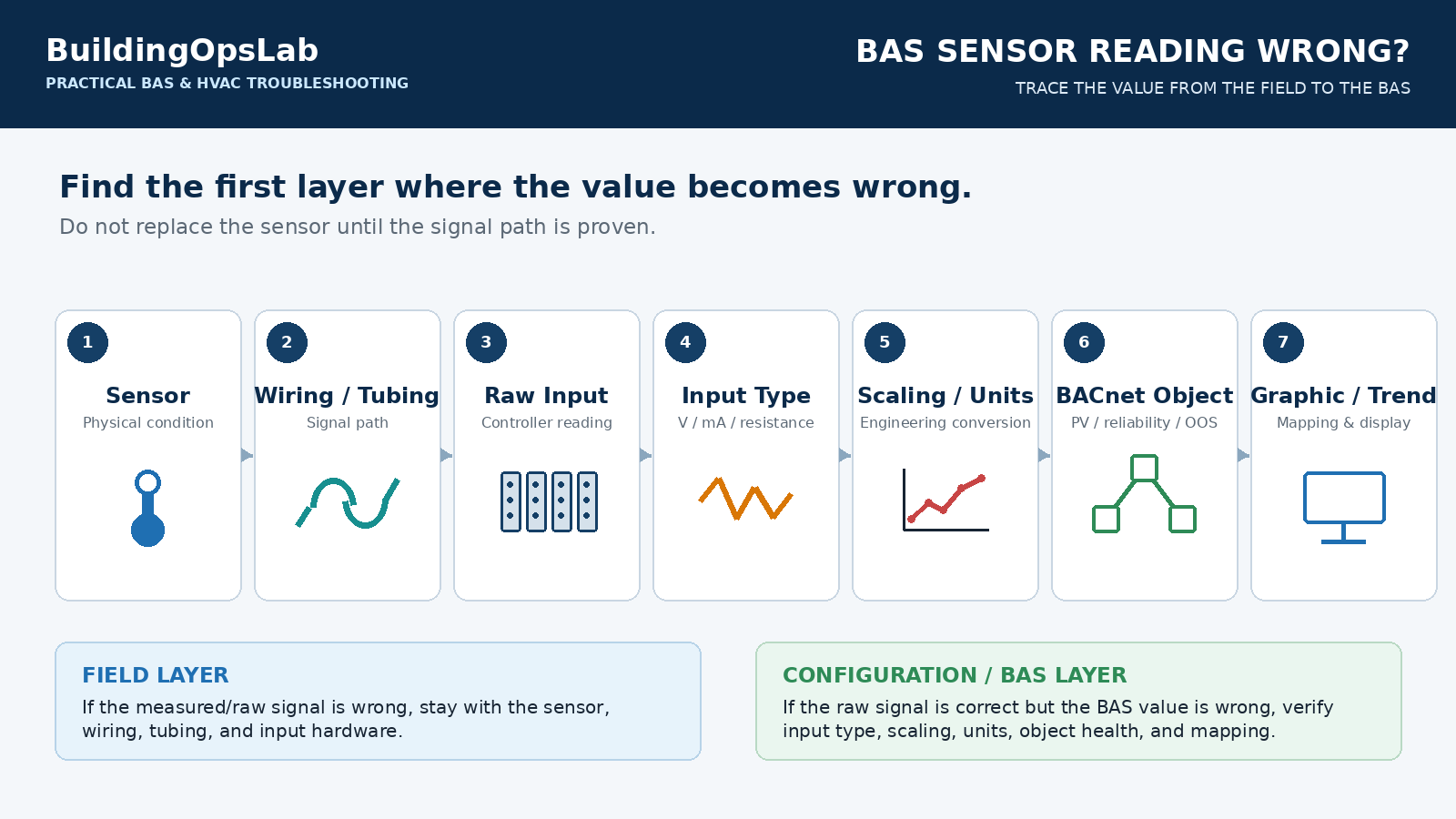
The fastest way to diagnose a questionable sensor is to follow the measurement path: physical sensor, field wiring or tubing, controller input, signal type, scaling, BACnet object, and finally the graphic or trend. Each layer can create a different error.
Quick Answer
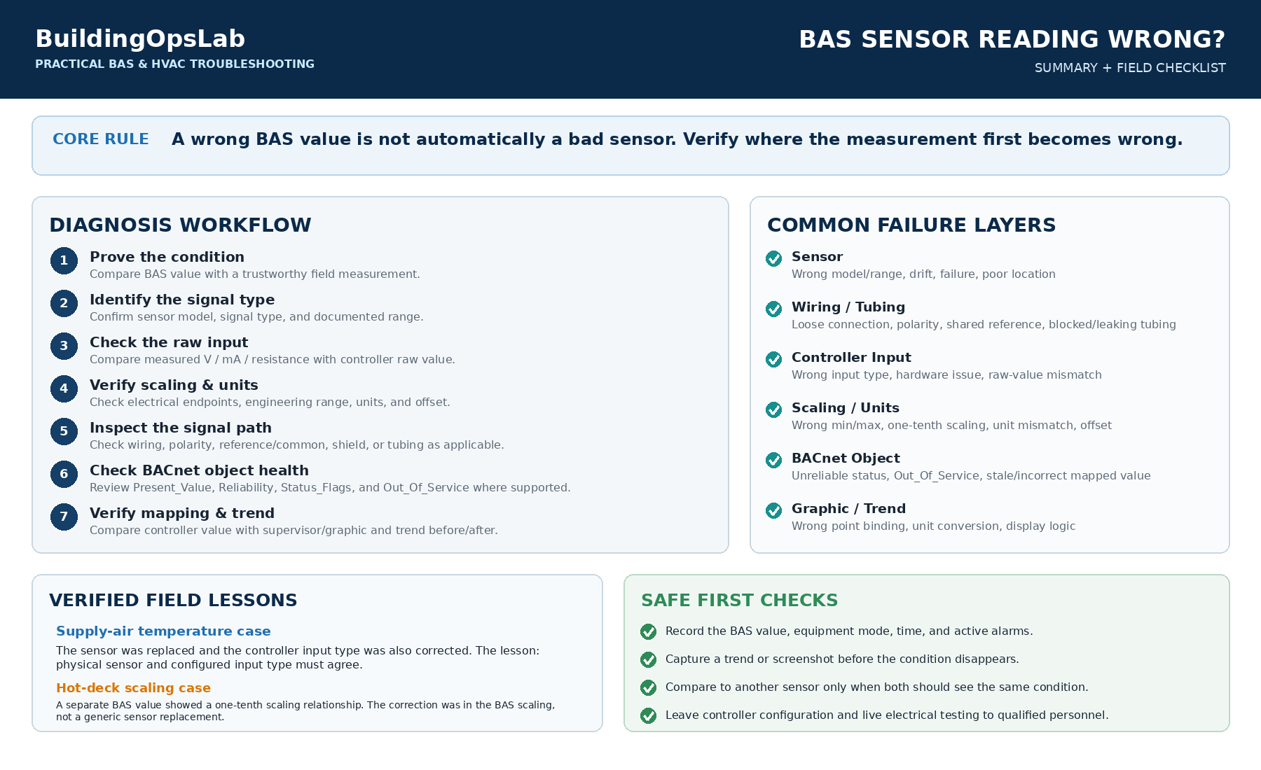
When a BAS sensor reading looks wrong, verify the measurement chain in this order:
- Confirm the physical condition with an independent measurement when practical.
- Identify the exact sensor signal type from the device documentation or nameplate.
- Verify the controller input is configured for that signal type.
- Check the raw electrical value before judging the scaled engineering value.
- Verify input range, output range, engineering units, and any offset or correction.
- Inspect wiring, polarity, reference/common, and tubing where applicable.
- Check BACnet Present_Value, Reliability, Status_Flags, and Out_Of_Service where supported.
- Trend the raw or hardware value and the final BAS value together if the platform exposes both.
The Problem Is Not Always the Sensor
A BAS point can be wrong even when the physical sensor is working. The fault may be in the sensing element, field wiring, controller hardware, I/O setup, linear scaling, unit conversion, BACnet object configuration, point mapping, or a software offset. Replacing the sensor before locating the bad layer can waste time and create a second problem without fixing the first.
Ask one question: Where does the value first become wrong? If the electrical signal is wrong at the controller terminals, stay in the field layer. If the raw signal is correct but the engineering value is wrong, move into input configuration and scaling. If the controller value is correct but the supervisor is wrong, investigate integration and mapping.
1. Prove the Reading Is Actually Wrong
Start with reality. Compare the BAS value with a trustworthy field measurement taken under conditions that make the comparison meaningful. For temperature, allow a calibrated reference to stabilize near the installed sensor. For pressure or differential pressure, verify that the reference instrument is measuring the same process and sensing locations as the BAS device.
ASHRAE commissioning guidance emphasizes that critical sensors should be verified as calibrated before BAS data is relied on for testing. The same principle applies to troubleshooting: do not tune a control loop around a number that has not been proven.
2. Identify the Sensor Signal Type Before Changing Anything
The controller must interpret the same electrical signal the sensor is actually producing. Common HVAC input types include resistance-based temperature sensors, voltage transmitters, and current transmitters. The Siemens ELC.E12D documentation, for example, lists Ni1000, Pt1000, NTC10K, 0-10 V, and 0/4-20 mA as configurable input types on universal I/O hardware.
A resistance sensor configured for the wrong curve can produce a believable but incorrect temperature. A voltage or current transmitter will also be misinterpreted if the input is configured for a different signal type. Verify the controller model and its documentation rather than choosing the closest-looking option in software.
3. Check the Raw Signal Before the Engineering Value
If the controller or commissioning tool exposes a hardware value, raw value, voltage, current, or resistance, compare it with an independent meter and the sensor documentation. This separates the field circuit from the software conversion.
For a 0-10 V transmitter, compare the measured signal at the controller input with the raw value reported by the controller. For current loops or resistive sensors, use the manufacturer-approved measurement method and understand how the meter affects the circuit before testing.
If the field signal is correct at the input terminals but the BAS engineering value is wrong, the sensor itself is unlikely to be the first place to look.
4. Verify Scaling, Range, and Engineering Units
Linear transmitters require the controller to map an electrical range to an engineering range. Johnson Controls documents input-range and output-range attributes that define this linear conversion for signals such as 0-10 V and 4-20 mA. Siemens similarly exposes signal-range and measurement-range values for configurable analog inputs.
A linear transmitter scaled for the wrong engineering range can be perfectly stable and still read high or low by a consistent factor. Wrong display units can create a similar symptom. Display precision changes only the number of decimal places; it does not repair an incorrect conversion.
Before changing scaling, record the existing configuration and verify the transmitter’s actual range. Never infer a pressure or temperature range from another sensor that happens to look similar.
5. Inspect Wiring, Polarity, Reference, and Tubing
Intermittent or noisy readings often point toward the field connection. Check terminals, conductor condition, polarity where applicable, shared commons or references, shields, and renovation splices. Compare the wiring with the sensor and controller diagrams instead of wire color.
For differential-pressure transmitters, the sensing path is part of the measurement. Verify high and low ports, tubing condition, leaks, kinks, trapped air or fluid where relevant, and whether the pickup locations still represent the intended system condition. A correct controller configuration cannot compensate for a bad pressure path.
6. Check BACnet Object Health, Not Just Present Value
On BACnet systems, Present_Value is only part of the story. Where supported, review Reliability, Status_Flags, and Out_Of_Service. BACnet defines Reliability so a device can indicate conditions such as over-range, under-range, open-loop, shorted-loop, no-sensor, or other unreliable states, although the exact set implemented varies by device.
Out_Of_Service deserves special attention. On input objects that support it, the property can decouple Present_Value from the physical hardware for testing or simulation. If it is left active, the BAS may show a convincing value that is no longer coming from the sensor.
7. Do Not Use an Offset to Hide a Configuration Error
Many BAS platforms provide a field offset or correction value. That can be legitimate when used according to manufacturer procedures to compensate for a known, measured bias. It should not be the first response to a large unexplained error.
If the sensor curve, transmitter range, or units are wrong, an offset may make the point look correct at one condition while leaving it wrong elsewhere. Fix the measurement model first; use calibration corrections only after the sensor type, wiring, raw signal, and scaling are verified.
8. Use Trends to Identify the Type of Error
A trend can reveal fixed bias, scaling error, noise, dropouts, or mapping problems. Trend the suspect point with a related physical variable and, when available, the raw input or hardware value.
A constant bias suggests a different failure than an error that grows with the process. Sudden jumps may indicate wiring or interference, while a stable controller value paired with a wrong graphic points toward integration or mapping.
Real-World Field Examples: Two Different Errors, Two Different Fixes
At one commercial AHU, a supply-air-temperature issue required both field and controller-side correction. The sensor was replaced, and the controller input type was corrected. The important lesson is not that every questionable SAT sensor should be replaced; it is that the physical sensor and the configured input type must agree before the BAS value can be trusted.
At another site, a hot-deck value had a scaling problem that produced a one-tenth relationship to the intended value. The correction was in the BAS scaling rather than a generic sensor replacement. These two cases looked similar from the operator screen – a bad number – but the failed layer was different.
That distinction is the basis of efficient sensor troubleshooting: prove whether the error starts in the field signal, the controller conversion, or the supervisory presentation before replacing hardware.
What these cases establish: the AHU work included a sensor replacement and an input-type correction; the hot-deck case involved scaling. This published case summary does not include the sensor model, raw measurements, or before-and-after temperature records. It therefore does not establish which AHU correction alone resolved the error, or provide a numerical calibration result to copy to another system.
What Facility Managers Can Check Safely
Facility teams can collect useful evidence without changing controller configuration or opening live electrical circuits:
- Record the BAS value, time, equipment mode, and active alarms.
- Compare the reading with another installed sensor serving the same area only if the two sensors should reasonably see the same condition.
- Look for sudden step changes, flat-lined values, or values outside plausible operating ranges.
- Review recent maintenance, sensor replacement, controller replacement, renovation, or point-remapping work.
- Capture a trend screenshot before the problem disappears.
Technician Checklist
- Identify the exact sensor model and documented signal/range.
- Verify controller input type and engineering units.
- Compare field signal with controller raw/hardware value.
- Verify scaling endpoints and any offset/correction.
- Inspect wiring and tubing as applicable.
- Check BACnet Reliability, Status_Flags, and Out_Of_Service where available.
- Compare controller value with supervisor/graphic value.
- Trend before and after the correction and document the final configuration.
Key Takeaways
- A wrong BAS value does not automatically mean a bad sensor.
- Find the first layer where the value becomes wrong: sensor, wiring, input hardware, scaling, BACnet object, or graphic.
- Sensor type and controller input type must match.
- Linear transmitters require the correct electrical range and engineering range.
- Use offsets only after the measurement chain is proven.
- A reliable trend plus an independent field measurement is stronger evidence than a graphic alone.
FAQ
Can the wrong sensor type still produce a believable temperature?
Yes. A controller using the wrong resistance curve can produce a value that appears plausible but is biased or nonlinear. Verify the actual sensor type and the controller’s configured input type.
What if the BAS value is wrong but the measured 0-10 V signal is correct?
Move downstream into controller configuration and mapping. Check the controller’s input range, output range, units, offset, raw-to-engineering conversion, and the point mapped to the supervisor or graphic.
Should I calibrate the point with an offset?
Only after the sensor, wiring, signal type, raw value, and scaling have been verified. An offset should compensate for a known measured bias, not hide an unknown configuration error.
What does Out_Of_Service mean on a BACnet input?
Where supported, it can decouple the BACnet object’s Present_Value from the physical hardware for testing or simulation. The exact behavior is implementation-specific, so verify the controller documentation.
Related Articles
- BAS Graphic Says ON but the Equipment Is OFF: How to Verify Command, Status, and Feedback
- AHU Static Pressure Alarm Keeps Coming Back? What to Check First
- HVAC Pump Hunting: Why Your VFD Pump Keeps Speeding Up and Slowing Down
Sources & Further Reading
- Siemens — Configure Controller I/Os (ELC.E12D) — Universal input types and configurable signal/measurement ranges.
- Johnson Controls — Analog Input Attributes (Metasys UI Objects, Attributes, and Commands Reference Guide) — Input/output range scaling, field offset, hardware-related attributes, and Out Of Service.
- BACnet Committee — Reliability Property Addendum — BACnet Reliability concept and common input fault states.
- ASHRAE Handbook — HVAC Commissioning, Chapter 44 — Verification/calibration of critical sensors before relying on BAS readouts.
Safety Disclaimer
This article provides general commercial HVAC and building-automation information. Always follow manufacturer documentation, site-specific procedures, and applicable safety requirements.