BAS Graphic Says ON but the Equipment Is OFF: How to Verify Command, Status, and Feedback

A BAS graphic shows the fan ON, but the fan is not moving. A pump graphic shows 60%, but the VFD display says something different. A valve graphic says closed, yet the actuator is still open. These are common building-automation complaints, and the first mistake is assuming the graphic itself is proof of what the equipment is doing.
A graphic is a visualization of one or more data points. Whether that point represents a command, an internal software state, a physical output, a feedback input, or a true equipment proof depends on how the system was designed and mapped.
In This Guide
- Why “ON” Does Not Always Mean Running
- 1. Identify the Point Behind the Graphic
- 2. Separate Command from Status and Proof
- 3. Check BACnet Priority and Overrides
- 4. Check Out-of-Service, Reliability, and Communication State
- 5. Verify the Controller Output Physically
- 6. Verify the Feedback Circuit
- 7. Check Point Mapping and Graphic Binding
- 8. Trend Command, Status, and Proof Together
- Real-World Field Case: Pump Speed Graphic Did Not Match Operation
- Choose the Next Check from the Evidence
- How to Fix a BAS Graphic Mismatch
- BAS Command/Status/Feedback Checklist
- FAQ
- Key Takeaways
Quick Answer
When a BAS graphic does not match the equipment, identify exactly what point the graphic is displaying before replacing hardware or rewriting logic.
- Command: what the BAS is asking the equipment to do.
- Status: what a controller or device reports as its operating state.
- Proof/Feedback: a response signal whose meaning must be verified. An airflow switch, current switch, auxiliary contact, VFD run status, or position sensor proves different things; none should be treated as proof of every physical result.
- Graphic value: whatever object the graphic happens to be bound to; it may be any of the above.
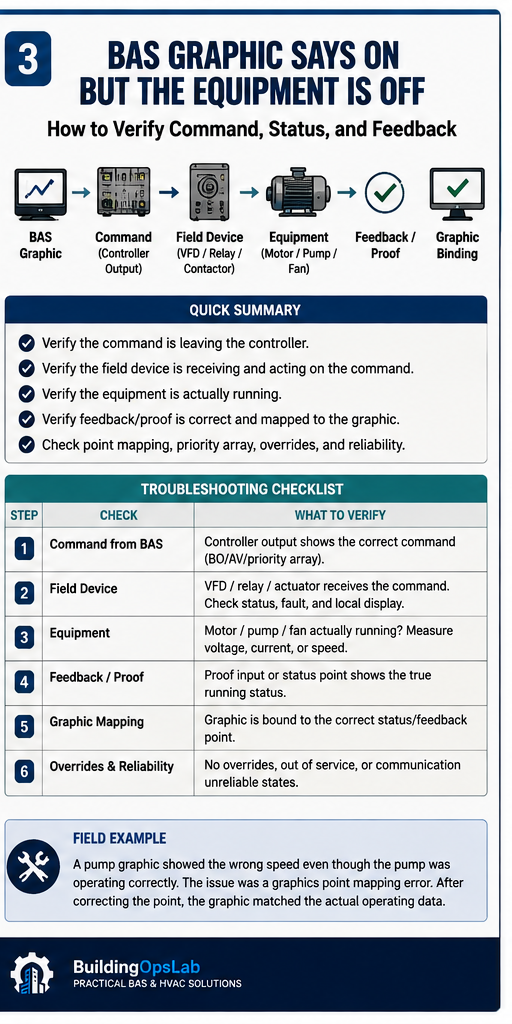
Why “ON” Does Not Always Mean Running
In BACnet and other BAS architectures, a Binary Output object is primarily a command interface. Johnson Controls documentation explicitly distinguishes a binary output command from feedback: a supply-fan BO can command ON, while a separate binary input such as an airflow switch is used to confirm airflow.
Modern packaged controllers may expose several related points at the same time. For example, Johnson Controls Verasys documentation lists Fan Command, Fan Status, Air Proving Switch, fan output percentage, and supply-air temperature as separate values. A graphic designer must choose which point drives the icon, label, color, animation, and alarm.
If the graphic is bound to Fan Command, it can legitimately display ON while the fan is physically off because a safety, VFD fault, local hand switch, failed contactor, broken output circuit, or mechanical failure prevented the command from producing the expected result.
1. Identify the Point Behind the Graphic
Open the graphic binding or point details. Do not rely on the label “Fan Status” or “Pump On” until you confirm the actual object reference.
- Object name and full path.
- BACnet object type: BI, BO, AI, AO, BV, AV, MSV, etc.
- Device or controller that owns the point.
- Present Value and Reliability.
- Whether the point is writable or read-only.
- Units, state text, scaling, and any graphic transformation.
- Last update or communication status, if the platform exposes it.
A mislabeled point can mislead operators for years because the graphic looks authoritative even when it is displaying the wrong object.
2. Separate Command from Status and Proof
For motor-driven equipment, build a simple command-to-proof chain.
- BAS command: Start/Stop or speed reference.
- Controller output: relay state or analog output.
- Interposing relay/contactor/VFD command input.
- Equipment response: VFD run state, motor current, auxiliary contact, airflow switch, pressure differential, or another independent proof.
- BAS feedback point: the signal returned to the BAS.
- Graphic display: the point selected to represent operation.
The point where the chain stops tells you where to troubleshoot. If the BAS command is OFF but the equipment is running, look for local control, a hardwired permissive, another controller, or a higher-priority command. If the BAS command is ON but the controller output never changes, troubleshoot the control logic or output hardware. If the output changes but there is no proof, move into the field device and mechanical/electrical system.
3. Check BACnet Priority and Overrides
Commandable BACnet objects can have multiple active commands at different priorities. The effective Present_Value comes from the highest active priority. A technician can issue a command that is accepted by the workstation but does not become effective because another command has higher priority.
Current Metasys UI documentation shows the Priority Array specifically so operators can determine which process controls a point. If the selected command is lower than an existing command, the system warns that the selected command will not take effect.
Check for operator overrides, emergency/safety commands, optimization routines, schedules, interlocks, local-control modes, and stale manual commands. Release overrides only when you understand why they exist.
4. Check Out-of-Service, Reliability, and Communication State
A point can look valid while being disconnected from the physical process. In many BACnet implementations, placing an object Out of Service allows its Present_Value to be manipulated independently of physical I/O. Reliability flags can also identify communication failure, open-loop conditions, or other faults.
If a graphic is displaying a stale or simulated value, changing the physical equipment will not necessarily update the screen. Confirm the point is in service, reliable, and communicating before trusting it.
5. Verify the Controller Output Physically
When safe and authorized, qualified technicians should verify the actual output at the controller rather than trusting the graphic. For a binary command, this may mean checking relay state and voltage at the output. For an analog command, compare the BAS percentage to the actual control signal and the receiving device’s displayed reference.
This step is especially useful when deciding whether the problem belongs to BAS or HVAC/electrical. If the BAS controller output correctly follows the command but the equipment does not respond, the investigation should move downstream instead of replacing the BAS controller without evidence.
6. Verify the Feedback Circuit
A status point is only as trustworthy as the device creating it. Review how the feedback is generated.
- Current switch around the motor conductor.
- Airflow proving switch or differential-pressure switch.
- VFD run-status relay or BACnet run status.
- Contactor auxiliary contact.
- Actuator position feedback.
- Flow switch or differential-pressure proof.
- Packaged-equipment internal status communicated over BACnet.
A failed proof device can make operating equipment appear off. A feedback point mapped to the command instead of the proof can do the opposite.
7. Check Point Mapping and Graphic Binding
If field operation and controller points are correct, inspect the graphic. Common problems include binding to the wrong object, copying a graphic from similar equipment without changing all references, stale database mappings after controller replacement, wrong scaling, reversed state text, or using a calculated value when a real feedback point exists.
A fast test is to open the raw point in the navigation tree and compare it with the value on the graphic at the same time. If the raw point is correct but the graphic is wrong, the problem is in the graphic binding or display logic, not the field equipment.
8. Trend Command, Status, and Proof Together
Trends can reveal whether the mismatch is constant or only occurs during transitions. Trend the command, feedback/proof, relevant safety or permissive points, and the equipment’s own run/fault status. If the command changes first and proof follows normally, the sequence is likely functioning. If proof drops while command remains ON, investigate the equipment or proof circuit. If the graphic alone disagrees with the raw trend data, investigate mapping.
Real-World Field Case: Pump Speed Graphic Did Not Match Operation
During troubleshooting of heating pumps that were hunting, the BAS controls and operating response were reviewed under multiple conditions. The main control problem was addressed separately, but verification uncovered another issue: the BAS graphic for Pump 1 speed did not match the actual operating data.
The graphic point was corrected so the displayed information matched the actual operating value. That finding was important because an incorrect graphic can send future troubleshooting in the wrong direction even when the mechanical equipment and controller are working.
The field lesson is simple: verify the source point before using a graphic as diagnostic evidence.
Choose the Next Check from the Evidence
Start with a read-only comparison of the graphic, raw point, local device indication, and an appropriate physical observation. The patterns below guide the next check; none identifies a failed component by itself.
The raw point and graphic disagree
Confirm that both views refer to the same device, object, units, and observation time. If the raw value is current and reliable, inspect the graphic binding, scaling, state labels, and refresh behavior. Preserve the original reference before correcting it. A display correction is complete when both views agree through an authorized operating transition, not just at one steady value.
The effective command changes, but the receiving device does not respond
Check local/remote selection, permissives, device faults, and the intended command source before assuming an output has failed. Qualified personnel can then compare the physical output with the receiving input using the equipment wiring documentation. Record the first point where expected and observed behavior diverge; do not bypass an interlock to force agreement.
The run indication is ON, but the required flow is missing
A run relay, motor-current switch, or actuator-position signal establishes only what that particular signal measures. It does not by itself establish useful airflow, water flow, or heating/cooling delivery. Verify the physical effect required by the approved sequence, then investigate the mechanical path or the proof device as the evidence warrants.
The mismatch appears only during starting or stopping
Compare timestamps, update rates, the equipment response, and configured proof delays before treating the event as a persistent failure. Johnson Controls’ FX SNC alarm-feedback documentation distinguishes command reference from status input and describes a reference delay after command changes. Use the actual platform and sequence settings; there is no universal delay suitable for every device.
What to keep in the completed service record
Save the object references, timestamped observations, operating mode, exact correction, and retest result. Verify the original complaint in automatic operation after temporary overrides are released. If the relevant load or transition did not occur during the visit, state what remains unverified and define the follow-up check.
How to Fix a BAS Graphic Mismatch
The fix depends on the failed layer. Correct the graphic binding if it references the wrong point. Correct point mapping if the database references the wrong BACnet object. Repair or replace a failed feedback device if the proof is wrong. Correct controller logic if command and feedback semantics are mixed. Repair the physical output circuit if the BAS output is correct but the equipment does not respond.
After any correction, test the equipment through a controlled start/stop or modulation sequence and verify command, output, feedback, and graphic display together.
BAS Command/Status/Feedback Checklist
- What exact point is the graphic displaying?
- Is it a command, status, proof, calculated value, or feedback?
- Is the point reliable and in service?
- Is a higher-priority BACnet command active?
- Is the equipment in Hand/Local or another non-BAS mode?
- Does the physical controller output follow the BAS command?
- Does the field device respond to that output?
- Does the feedback/proof signal change?
- Does the raw point match the graphic?
- Are command, status, and proof trended together?
FAQ
Why does the BAS show a fan ON when the fan is off?
The graphic may be showing the fan command rather than independent run proof. Check the graphic binding, controller output, VFD/contactor status, and the feedback device used to prove operation.
Can a BACnet Present Value be ON even if the physical output is not ON?
Yes, depending on object type and system state. A command object represents the effective commanded value, not necessarily independent physical proof. Out-of-service states, local controls, failed output circuits, or downstream faults can also separate the software value from the physical result.
Should a BAS graphic use command or status to animate equipment?
For an operating-state animation, independent status/proof is usually more meaningful than command alone. The best design often shows both: command and actual status, with an alarm or mismatch indication when they disagree.
How do I know whether the problem is BAS or HVAC?
Trace the command chain. If the controller output does not follow a valid BAS command, investigate BAS logic or controller hardware. If the controller output is correct but the equipment does not respond, move downstream to the VFD, relay, contactor, safety circuit, motor, actuator, or mechanical equipment.
Key Takeaways
- A BAS graphic is a visualization, not physical proof.
- Command, status, and proof should be treated as different signals.
- Check the BACnet Priority Array and overrides before assuming a command should take effect.
- Verify raw points and physical outputs before replacing equipment or controllers.
- Good graphics make command-versus-feedback mismatches visible instead of hiding them.
Related BuildingOpsLab Guides
- HVAC Pump Hunting: Why a VFD Pump Speeds Up and Slows Down
- VFD BACnet Integration: Why Start/Stop Commands Don’t Work
- BACnet Device Instance vs MAC Address vs Network Number
- VFD Running but BAS Says Off? Find Who Owns the Drive Command
- Fan Coil Unit Fan Not Running? Separate Motor, Relay, and BAS Faults
- Commercial HVAC Compressor Won’t Start: Command, Board, or Safety Fault?
- AHU Freezestat Tripped but Cooling Is Still On
Sources & Further Reading
- Johnson Controls — Binary Output Object Technical Bulletin: Feedback and proof
- Johnson Controls — Metasys UI 15.0: Commanding equipment and Priority Array
- Johnson Controls — Metasys Binary Output Attributes
- Johnson Controls — Verasys VEC100: Fan Command, Fan Status, and Air Proving Switch
- Johnson Controls — Alarm Feedback: Command Reference vs Status Input
Safety Disclaimer
This article provides general commercial HVAC and building-automation information. Always follow manufacturer documentation, site-specific procedures, and applicable safety requirements.