Fan Coil Unit Fan Not Running? How to Separate a Motor, Relay, and BAS Controller Fault
Start at the FCU Control Chain
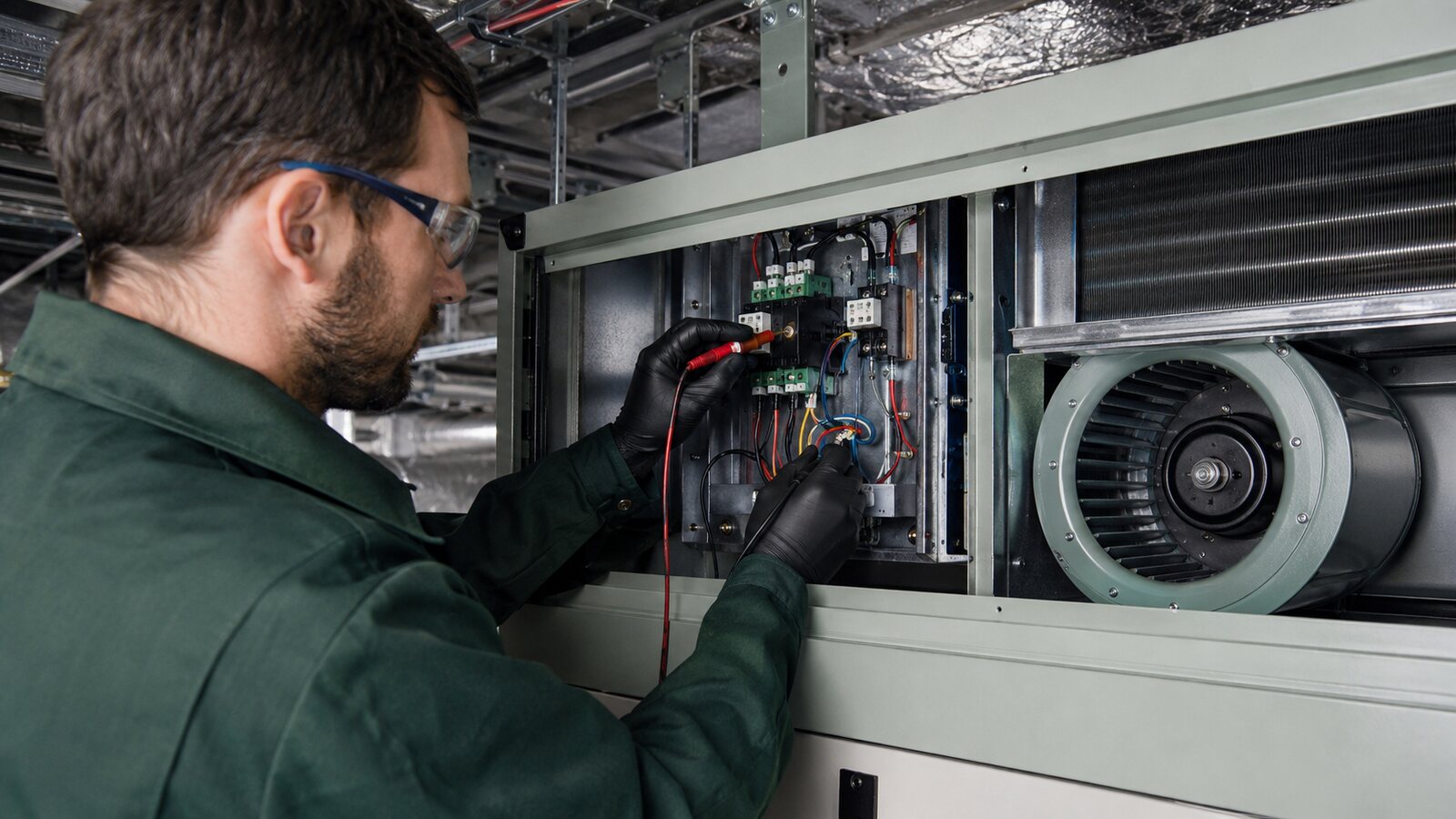
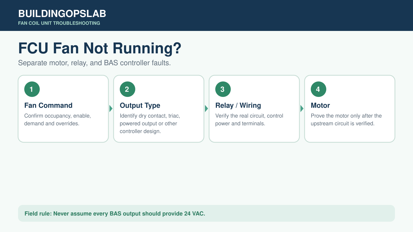
When an FCU fan does not run, do not assume the motor has failed. Confirm that the fan should be enabled, identify the controller’s actual output type, prove the relay and wiring circuit, then verify the correct power and control at the motor. A BAS ON indication may show only a software command.
FCU Fault-Isolation Map
- Confirm the no-airflow symptom
- Map the FCU fan control chain
- Trace the command from BAS to motor
- Match corrective action to the failed component
- Review a burned-output field case
- Complete the FCU verification checklist
- Review FCU troubleshooting questions
Symptom: Fan Command With No Airflow
A fan coil unit shows a fan command from the BAS, but there is no airflow. The fault may be in occupancy logic, the controller output, a relay or fan board, control power, field wiring, fan-speed selection, an ECM control signal, or the motor. Because FCU designs vary, identify the installed controller and motor before making assumptions about voltage or output behavior.
BAS demand → fan command → controller output → relay or control circuit → motor power and control → fan operation
Where the FCU Fan Chain Fails
BAS logic blocks fan operation
Occupancy, schedule, heating or cooling demand, fan mode, a window contact, condensate safety, freeze protection, local wall-controller mode, or an override may hold off the final output.
The software output changes but the hardware does not
Relay contacts, triacs, PCB traces, terminals, conductors, or external power sources can fail while the graphic still shows an ON command.
The output is tested as the wrong type
A dry contact does not generate voltage. Other controllers may switch external power, provide a powered binary output, use a triac, or send an analog or manufacturer-specific motor command.
A fan relay or relay board has failed
The controller may only command an intermediate relay. A healthy controller output can therefore be followed by burned contacts, a failed board, or missing control or line power.
The motor receives the wrong power or control
PSC, multi-speed AC, ECM, and manufacturer-specific motor packages require different tests and control signals.
Trace the Fan Circuit From BAS to Motor
Step 1 — Confirm the fan should be running
Check occupancy, unit enable, fan mode, demand, space conditions, alarms, safeties, overrides, and local-controller mode.
Step 2 — Identify the controller and output type
Record the controller model, output terminal, electrical rating, motor type, and wiring arrangement. Use the installed documentation.
Step 3 — Command the fan and observe the output
Where safe and permitted, command OFF and ON while observing the software value, output LED, relay action, and real circuit state.
Step 4 — Test the output in the installed circuit
Measure continuity or voltage according to the output design, verify external control power, inspect terminals, and confirm the output can drive the intended relay or load.
Step 5 — Check the fan relay or fan board
Verify control input, switched output, power source, contact condition, loose terminals, and speed interlocks.
Step 6 — Verify motor power and control
Qualified personnel should confirm the required electrical supply and control signal at the motor. Missing inputs mean the investigation remains upstream.
Step 7 — Test the motor by the manufacturer procedure
If the motor runs correctly during an approved independent test, the failure is upstream. If correct supply and control reach the motor and it still fails, investigate the motor assembly.
Corrective Action by Failure Point
BAS programming problem
Correct the schedule, occupancy logic, fan enable, sequence, mode, or override and verify automatic operation.
Failed controller output
Prove the hardware fault electrically and confirm the connected load is appropriate before replacing the controller or I/O hardware.
Burned terminal or damaged wiring
Identify and correct the cause, such as a loose connection, excessive current, incorrect load, or short circuit, before installing replacement hardware.
Failed relay or fan board
Replace the failed component only after proving the control input and downstream load circuit.
Failed motor
Identify the motor type and verify that required power and control are present before replacement.
Field Case: Burned Controller Output Terminal
A commercial fan coil unit was reported with no fan operation. The fan motor was tested and confirmed capable of operating, so the investigation moved upstream. The BAS controller’s fan-output section was then checked and a damaged, burned output terminal was found. The defensible diagnosis was not a failed motor; it was a working motor that could no longer receive a reliable controller output. Controller replacement was recommended, along with verification of the connected load and wiring so the replacement would not be exposed to the same cause.
FCU Fan Verification Checklist
- ☐ Confirm occupancy, unit enable, fan mode, demand, alarms, and overrides
- ☐ Identify the controller model and exact fan-output terminal
- ☐ Identify whether the output is relay, triac, powered binary, analog, or manufacturer-specific
- ☐ Review the wiring diagram before measuring
- ☐ Observe output status and relay action during commands
- ☐ Verify the physical output in the installed circuit
- ☐ Check external control power and relay or fan-board operation
- ☐ Inspect for loose or burned terminals
- ☐ Identify the motor type before testing it
- ☐ Verify required power and control at the motor
- ☐ Monitor operation after repair
FCU Fan Troubleshooting FAQ
My BAS says the FCU fan is ON. Is the controller bad?
Possibly, but the point may be only a command. Verify the physical output, relay circuit, power, and motor before assigning the failure.
Should every BAS fan output show 24 VAC?
No. Some controller outputs are dry contacts and do not source voltage. Others switch external power or provide a powered output.
Can an FCU controller power the motor directly?
Some purpose-built controllers can switch fan circuits within their ratings; others require external relays or dedicated motor controls. Use the installed documentation.
How do I separate a motor fault from a BAS fault?
Prove whether the motor can operate using the manufacturer procedure, then work upstream through the relay and controller output if it can.
Why would an output terminal burn?
Possible causes include a loose connection, excessive current, an incorrect load, or an electrical fault. Correct the cause before reconnecting replacement equipment.
Related FCU and BAS Guides
- BAS Graphic Says ON but Equipment Is OFF
- VAV Box Not Cooling
- Commercial HVAC Preventive Maintenance Checklist
Technical Source
Technical references used to validate this troubleshooting framework. Manufacturer-specific values and procedures apply only to the equipment identified in the referenced documentation.
Safety Disclaimer
This guide is for general educational use by qualified building-automation, HVAC, and electrical personnel. Follow the installed manufacturer documentation, site procedures, applicable codes, lockout/tagout requirements, and required personal protective equipment. Do not bypass safety devices or perform energized testing unless you are trained, authorized, and the procedure specifically requires it.