0-10 V vs 2-10 V Actuator Control: Why a Valve or Damper Won’t Fully Close
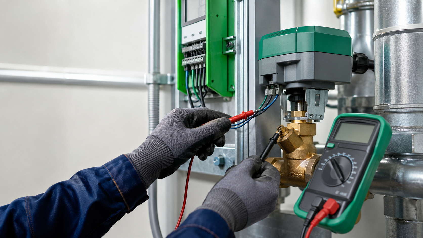
A valve or damper that will not fully close is often blamed on the actuator first. But if the actuator is modulating smoothly and consistently stops short of the commanded end position, the control-signal range deserves an immediate check.
The most common comparison is 0-10 VDC versus 2-10 VDC. Both are widely used for modulating HVAC actuators, VAV controllers, valves, and dampers. They look similar on a BAS graphic because both can be displayed as 0-100%, but electrically they are not the same mapping.
Siemens and Johnson Controls documentation shows current HVAC actuators that can be configured for either 0-10 V or 2-10 V operation. The important commissioning rule is simple: the BAS output scaling must match the actuator input configuration.
In This Guide
- Quick Answer
- What 0-10 V and 2-10 V Actually Mean
- Expected Voltage and the Next Diagnostic Step
- 1. Confirm the Actuator Signal Type
- 2. Verify BAS Analog-Output Scaling
- 3. Measure the Voltage at Both Ends
- 4. Compare Command with Position Feedback
- 5. Check Mechanical Travel and Calibration
- Real-World Field Case: Cooling Valve Would Not Fully Close
- How to Diagnose a Valve or Damper That Will Not Fully Close
- Common Mistakes
- FAQ
- Key Takeaways
- Sources & Further Reading
Quick Answer
When a valve or damper will not reach 0% or 100%, verify the signal path before replacing hardware:
- Confirm the actuator’s required control range from the actual model documentation.
- Confirm BAS analog-output configuration: 0-10 V, 2-10 V, direct/reverse, and min/max limits.
- Measure voltage at 0%, 50%, and 100% command.
- Measure at the actuator terminals, not only at the controller.
- Check signal common/reference and wiring polarity.
- Compare position feedback or mechanical stroke with the commanded position.
- Verify calibration, linkage, valve seating, and damper stops.
What 0-10 V and 2-10 V Actually Mean
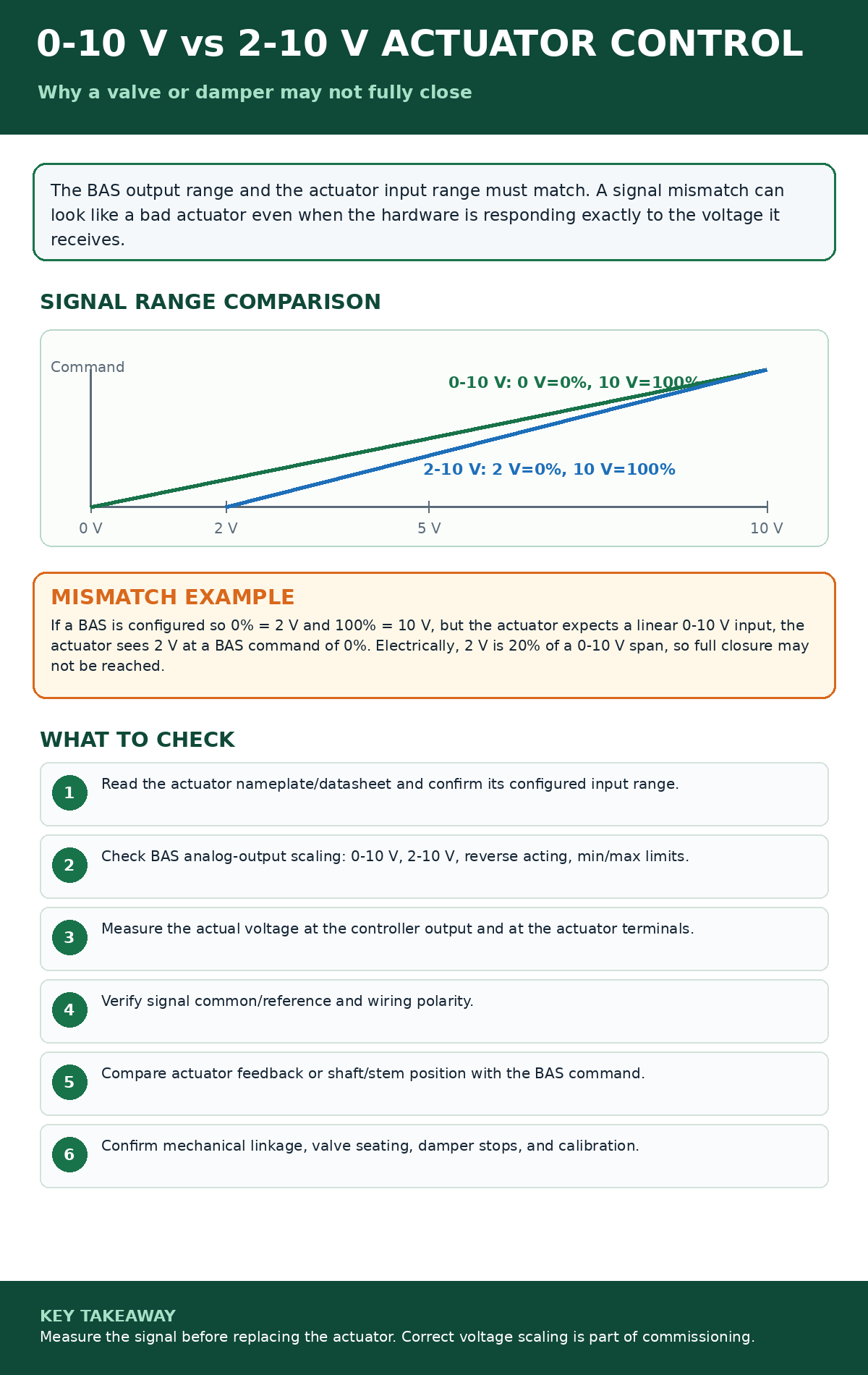
For a simple direct-acting 0-10 V input, 0 V represents the low end of the commanded range and 10 V represents the high end. For a direct-acting 2-10 V input, 2 V represents the low end and 10 V represents the high end.
If the controller is configured for 2-10 V, a BAS command of 0% typically produces 2 V. If the connected actuator is actually configured as a linear 0-10 V device, that 2 V is 20% of the electrical span. The actuator can therefore stop short of full closure even though the BAS screen says 0%.
The reverse mismatch is also possible: a controller may produce 0-10 V while the actuator expects 2-10 V. What the actuator does below 2 V is manufacturer-specific. Some devices use 0 V as a special override or full-close condition; others treat the dead range differently. Do not generalize behavior across models.
Expected Voltage and the Next Diagnostic Step
This reference assumes a linear, direct-acting voltage command with no minimum limit, split range, or override. The numbers are calculated electrical mappings, not measurements from the field case. Confirm the installed actuator configuration before using them.
| Command | 0–10 V | 2–10 V |
|---|---|---|
| 0% | 0 V | 2 V |
| 25% | 2.5 V | 4 V |
| 50% | 5 V | 6 V |
| 75% | 7.5 V | 8 V |
| 100% | 10 V | 10 V |
Calculation: voltage = lower endpoint + (command ÷ 100) × electrical span. Thus a 50% command is 6 V on a 2–10 V range. Conversely, 6 V is 60% of a 0–10 V span but 50% of a 2–10 V span. Electrical percentage is not automatically valve-flow percentage or damper-airflow percentage.
The controller voltage differs from the expected mapping
Check the effective command, output type, range, direct/reverse action, clamps, and overrides. Document the active configuration before changing it. A mismatch identifies a question about the command/output path; it does not alone prove that the controller hardware failed.
The controller voltage is correct, but the actuator signal differs
Have qualified personnel verify the measurement reference and signal path against the installed wiring diagram. Record both measurement locations and the operating state. Do not assume that chassis ground is the required signal common, or that the same terminal labels apply to every actuator.
The actuator receives the expected signal, but travel is wrong
Check the configured input range, direction, calibration, mounting, and coupling. The Johnson Controls VA9208-GGx-x instructions, Setup and Adjustments, illustrate why these are separate checks: range selection, direct/reverse response, and calibration of reduced travel affect operation. Apply the procedure for the actual installed model.
Travel reaches the closed position, but the complaint remains
Verify the physical effect and valve or damper condition under the approved test conditions. Shaft position alone does not prove a leak-tight valve seat or zero airflow. Record the evidence for closure separately from the evidence that unwanted heating, cooling, or airflow stopped.
Close out the test: retain the original and final settings, command and measured voltage pairs, observed travel, available feedback, and the operating result. Define tolerances from manufacturer specifications and the measurement method; do not invent a universal pass/fail voltage. Release temporary overrides and verify automatic operation.
1. Confirm the Actuator Signal Type
Read the actuator nameplate, wiring diagram, configuration switch position, software setup, or official datasheet. Do not identify the signal range from wire color alone.
Current Siemens OpenAir documentation shows modulating actuators with selectable 0-10 V or 2-10 V signals. Johnson Controls documentation also lists proportional actuators that accept either 0-10 V or 2-10 V input. Because many actuators are configurable, the product family name is not enough; verify the actual installed configuration.
2. Verify BAS Analog-Output Scaling
Open the controller output configuration and check more than the graphic percentage. Confirm the physical output type and scaling.
- Is 0% mapped to 0 V or 2 V?
- Is 100% mapped to 10 V?
- Is the output direct acting or reverse acting?
- Are minimum or maximum output limits applied?
- Is there a software clamp, minimum position, or sequence override?
A graphic showing 0% is only a software value. The meter tells you what the actuator is actually receiving.
3. Measure the Voltage at Both Ends
Command several controlled positions and measure the analog signal. A useful test is 0%, approximately 50%, and 100%, provided the equipment can be safely exercised.
Measure first at the BAS output and then at the actuator terminals. A correct voltage at the controller does not prove the same voltage arrives at the actuator. Check for wiring resistance, loose terminations, poor common reference, polarity errors, induced noise, or incorrect field splices.
4. Compare Command with Position Feedback
Many proportional actuators provide an analog feedback signal, often called U, position feedback, or actual position. Do not assume the feedback range is identical to the command range. A device may accept one input range and provide a different feedback range.
Use feedback as one piece of evidence. If the BAS commands 0%, output voltage is correct, and feedback shows the actuator remains partially open, inspect calibration and mechanics. If the feedback says 0% while the valve is physically open, investigate feedback scaling or mechanical coupling.
5. Check Mechanical Travel and Calibration
Electrical scaling is not the only reason an actuator stops short. A shaft can slip, a linkage can be misadjusted, a valve stem can bind, a damper can hit a mechanical stop, or an actuator can be installed with the wrong rotation or stroke setup.
After the electrical signal is verified, watch the actuator through its full safe travel. Confirm that the mechanical end position matches the control end position.
Real-World Field Case: Cooling Valve Would Not Fully Close
At one commercial site, the cooling-valve actuator was modulating, but it appeared not to fully close when the BAS commanded 0%.
The actuator itself used a 0-10 VDC control signal, while the BAS program was configured for a 2-10 VDC output range. With that mismatch, the BAS could display 0% while still delivering the minimum voltage of the 2-10 V range.
The BAS output configuration was corrected to 0-10 VDC and the actuator operation was tested afterward. This case is a strong reminder that a modulating actuator can be mechanically healthy while the control system is sending the wrong electrical range.
How to Diagnose a Valve or Damper That Will Not Fully Close
- Verify the physical valve or damper position before trusting the graphic.
- Identify the exact actuator and signal range.
- Check BAS output scaling and any output limits.
- Measure actual voltage at the BAS output.
- Measure the same signal at the actuator.
- Check actuator feedback and calibration.
- Inspect linkage, coupling, stem/shaft travel, and mechanical stops.
- Retest at 0%, midrange, and 100% after corrections.
Common Mistakes
Assuming 0% on the graphic means 0 V
It does not. A 2-10 V output normally maps the low end of the software command to 2 V.
Replacing the actuator before measuring the signal
If the actuator responds consistently to the voltage it receives, replacement may not solve the real problem.
Assuming all 2-10 V actuators behave the same below 2 V
They do not. Manufacturer-specific configuration determines how the dead range, override, or fail behavior is handled.
Ignoring feedback scaling
Input command range and output feedback range may be different. Verify both.
FAQ
Does 2-10 V mean the actuator is 20% open at 2 V?
Not when the actuator itself is configured for 2-10 V. In that configuration, 2 V is normally the low end of the control range. The 20% issue occurs when a 2 V minimum signal is sent to a linear actuator that actually expects 0-10 V.
Can 0 V mean full close on a 2-10 V device?
It can on some products or applications, but that behavior is manufacturer-specific. Verify the exact datasheet or configuration.
Why does my BAS show 0% but the valve still passes water?
Possible causes include output-range mismatch, minimum output limits, mechanical leakage, valve-seat damage, actuator calibration, linkage problems, or incorrect feedback/mapping.
Key Takeaways
- 0-10 V and 2-10 V are different electrical mappings even when the BAS displays both as 0-100%.
- Measure voltage before replacing an actuator.
- Verify the configured range on both the controller and actuator.
- Input and feedback ranges may not be identical.
- Finish commissioning by verifying actual mechanical end positions.
Related BuildingOpsLab Guides
- BAS Graphic Says ON but the Equipment Is OFF
- VAV Box Not Cooling? BAS and Airflow Checks
- RTU Economizer Not Working? Diagnose Sensors, Dampers, and Logic
Sources & Further Reading
- Siemens – OpenAir Non-Spring Return Damper Actuators
- Siemens – GDD/GLD Modulating Damper Actuator Data Sheet
- Johnson Controls – M9220-GGx-3Z Proportional Electric Spring Return Actuator Wiring
- Johnson Controls – VA9208-GGx-x Series Proportional Valve Actuator Setup and Adjustments
Safety Disclaimer
This article provides general commercial HVAC and building-automation information. Always follow manufacturer documentation, site-specific procedures, and applicable safety requirements.